nand2tetris Project 5 (Computer architecture)
Project 05 | nand2tetris
ちょくちょく進めてきたnand2tetris。ついにHack computerを実装するところまできたけど、Unit3までよりもややこしいので復習しやすいようにメモを残しながらやってみる。
やるべきことは、今まで作ってきたALUやRegister, Program Counterなどのパーツを使って、
- Hack CPU
- Memory
の実装をする。ROMはやらなくていい。
CPU

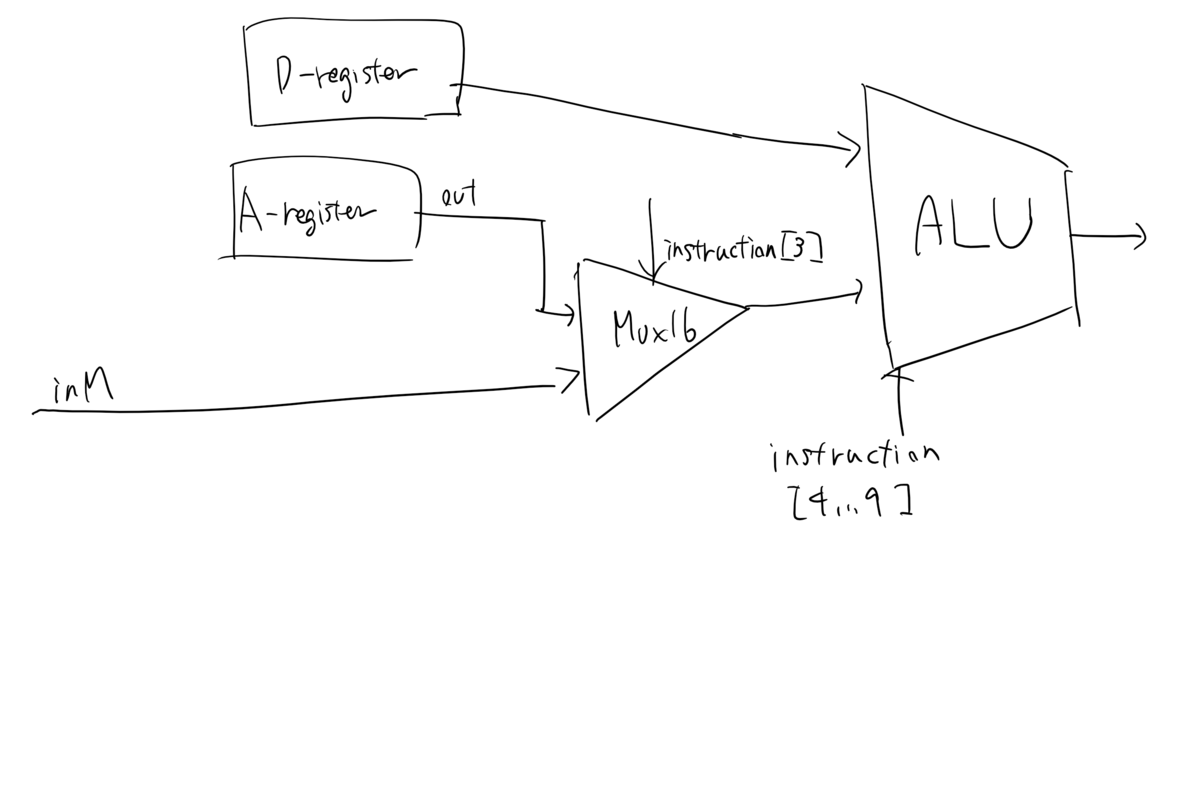
Chapter4のHack Machine Languageの仕様(特にc-instructionの仕様)を見ながらやっていく。大まかな構成は上の図に書いてあるのでcontrol bitの部分をどうすればいいか考えていく感じ。パーツになるRegisterとかPCのinterfaceもうろ覚えになってきているので復習しながらやる必要がある。
パーツのAPI

A-register
まずA-registerの部分(左上)。
- a-instructionに対してはinstructionの下位15bitをA-registerにloadしたい、のだが下位15bitといってもa-instructionの場合MSBが0と約束しているのでinstructionをそのまま入れればよくて、その場合Mux16のsel = 0でA-registerのload=1にしたい
- c-instructionに対してはA-registerのinに入れるのはALU outputそのままでよい。いつ更新すればいいかというと、c-instructionかつ1つ目のdestination bitが1のとき。(destination bitは順番にAMDを更新するかどうかを表すので)
- なのでA-registerのloadは式で書くと
load = if a-instructoin
              then 1
              else destination-M
のようになるのでMuxでそうなるようにする。結局次のようになりそう。

NOTつかわないでtrueをフィードしてもいいのか。(むしろそれがふつうっぽい)
ALUのまわり
c-instructionのときの6つのcビットはそのままALUのコントロールビットに入れていい。APIが同じなので。
c-instructionの仕様として、aビット(instruction[3])が0か1かによってALUのYがA-registerなのかM-registerなのかを変えるようになっているので、ALUの前のMultiplexorでそれを切り替える。

a-instructionのときALUに変な入力が入ることになるけど、ALU-outputを使う側でa-instructionのときは「何もしない」をすればよいので、気にしなくていい。
D-registerのloadにはinstructionのdestination bitとc-instructionのフラグ(つまり、instruction[0])のANDを入れればよい。writeMも同様。ここは難しくないので書かない。
PCのまわり
あとよくわからないのはPCの周りなのでそれを考える。というかPCの仕様を忘れたのでまずそれを思い出す。

loadとincフラグがあって両方立っているときはloadが優先される。reset > load > incという優先順位で制御されるらしい。
resetでもjumpでもないときは次のinstructionを読みに行きたいのだからincはtrueで固定してよさそう。resetはCPUのinであるresetをそのまま入れればよい。PCのinにはA-registerのoutをそのままいれればよい。結局難しいのはloadになにをフィードすればよいかだけだ。
必要な情報は、c-instructionのjmpビットの仕様と、ALUのoutであるzrとngの仕様である。jumpビットの仕様を確認して疑似コードを書いてみよう。

と思ったんだけど、jumpビットの仕様がきれいに定義されていて、各ビットごとに「outが <0, ==0, >0のときにjumpするかどうか」という形で記述されている。よって、jumpするかどうかは、
- j1 == 1 and out < 0
- j2 == 1 and out == 0
- j3 == 1 and out > 0
のORを取ればよいことが分かった。 out < 0 と out == 0はそれぞれALUのngとzrであり、out > 0はNot(Or(ng,zr))である。 ただし、a-instructionのときはjumpしたくないので、instructionのMSBとAndしなければいけない。
実装してみる
実装してみて気づいたがbitの番号が思ってたのと逆だった。でも図を書き直すのは面倒なので書かない。
// This file is part of www.nand2tetris.org
// and the book "The Elements of Computing Systems"
// by Nisan and Schocken, MIT Press.
// File name: projects/05/CPU.hdl

/**hdl
 * The Hack CPU (Central Processing unit), consisting of an ALU,
 * two registers named A and D, and a program counter named PC.
 * The CPU is designed to fetch and execute instructions written in
 * the Hack machine language. In particular, functions as follows:
 * Executes the inputted instruction according to the Hack machine
 * language specification. The D and A in the language specification
 * refer to CPU-resident registers, while M refers to the external
 * memory location addressed by A, i.e. to Memory[A]. The inM input
 * holds the value of this location. If the current instruction needs
 * to write a value to M, the value is placed in outM, the address
 * of the target location is placed in the addressM output, and the
 * writeM control bit is asserted. (When writeM==0, any value may
 * appear in outM). The outM and writeM outputs are combinational:
 * they are affected instantaneously by the execution of the current
 * instruction. The addressM and pc outputs are clocked: although they
 * are affected by the execution of the current instruction, they commit
 * to their new values only in the next time step. If reset==1 then the
 * CPU jumps to address 0 (i.e. pc is set to 0 in next time step) rather
 * than to the address resulting from executing the current instruction.
 */

CHIP CPU {

    IN  inM[16],         // M value input  (M = contents of RAM[A])
        instruction[16], // Instruction for execution
        reset;           // Signals whether to re-start the current
                         // program (reset==1) or continue executing
                         // the current program (reset==0).

    OUT outM[16],        // M value output
        writeM,          // Write to M?
        addressM[15],    // Address in data memory (of M)
        pc[15];          // address of next instruction

    PARTS:
    // Put your code here:
    //A Register
    Mux16(a = instruction, b = ALUOut, sel = instruction[15], out = ARegisterIn);
    Mux(a = true, b = instruction[5], sel = instruction[15], out = ARegisterLoad);
    Register(in = ARegisterIn, load = ARegisterLoad, out = ARegisterOut, out[0..14] = addressM);

    //ALU
    Mux16(a = ARegisterOut, b = inM, sel = instruction[12], out = AorMRegister);
    ALU(x = DRegisterOut, y = AorMRegister, zx = instruction[11], nx = instruction[10], zy=instruction[9],ny=instruction[8],f=instruction[7],no=instruction[6], out = ALUOut, out = outM, zr = ALUzr, ng = ALUng);

    //D-register
    And(a = instruction[4], b = instruction[15], out = DRegisterLoad);
    DRegister(in = ALUOut, load = DRegisterLoad, out = DRegisterOut);

    //writeM
    And(a = instruction[15], b = instruction[3], out = writeM);

    //Around Program Counter
    //construction of load bit
    And(a = instruction[2], b = ALUng, out = jumpIfNegative);
    And(a = instruction[1], b = ALUzr, out = jumpIfZero);
    Or(a = ALUng, b = ALUzr, out = ALUNotPositive);
    Not(in = ALUNotPositive, out = ALUpositive);
    And(a = instruction[0], b = ALUpositive, out = jumpIfPositive);
    Or(a = jumpIfNegative, b = jumpIfZero, out = jumpGE);
    Or(a = jumpGE, b = jumpIfPositive, out = jumpIfCInstruction);
    And(a = jumpIfCInstruction, b = instruction[15], out = jump);
    //Program counter
    PC(in = ARegisterOut, inc = true, load = jump, reset = reset, out[0..14] = pc);
}
これでCPU.tstが通ったのでCPUの課題はクリア。 時間がかかったのでMemoryとComputerはまた今度。